The BRCK GPIO Expansion – Datasheet
A unique feature of the BRCK is that it can be modded and extended with other hardware through it’s GPIO port (on the bottom of the device). Simply put, this allows you to connect any type of sensor, machine or device to the BRCK. We’ve built this to be as open and usable as possible, so it’s built to be Arduino compatible and we’re publishing all of the information on it.
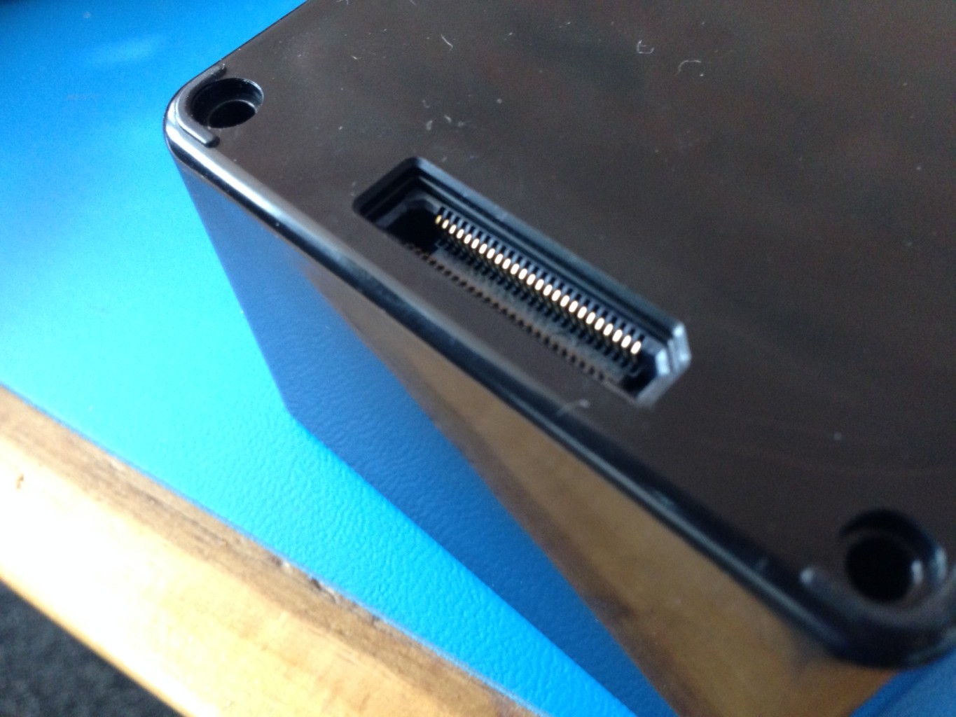
The BRCK GPIO expansion port
What you do with this is limited to your imagination and ability. Some ideas we’ve had include:
- Sensing (temperature, sound, motion, pressure, light, C02 etc.)
- Geo-logging/GPS
- Waterflow sensors
- Fingerprint scanner
- Weather or soil data
- Extra hard-drive space
- Extra ports
- Extra battery
- Satellite plug-in
I’m sure you’ll come up with more.
Keep in mind that because of the BRCK Cloud, you can also remotely monitor and manage these implementations and gather the data from them back to your own database for analysis, dashboard or other visualizations.
BRCK GPIO pinout diagram
Description
The BRCK 50-pin GPIO expansion is based on the Arduino compatible programmable ATmega32U4 8-bit AVR microprocessor. The microprocessor has a 16MHz crystal oscillator, 32KB of flash memory, 2.5KB of SRAM and 1KB of EEPROM.
The expansion pins include 19 general purpose input/output (PWM outputs, analog and digital pins), a USB port and hardware serial ports which support I2C UART and SPI communication modes. In addition, there is a power input port (4-18V) and two 5V power outputs (one via USB) with maximum supply current of 500mA.
The desired hardware expansion can be connected to the relevant expansion pins and an Arduino sketch for the application can be uploaded directly through the BRCK cloud.
AVAILABLE FEATURES
- Arduino-compatible Programmable 8-bit AVR Expansion Controller
- 32 KB flash memory, 2.5KB SRAM, 1KB EEPROM
- Programming of flash, EEPROM, fuses and lock bits through JTAG interface
- Standardized 50-pin connector with open-hardware pin-out
- 19 General Purpose I/O pins (A/D pins, PWM outputs, etc.)
- Two 5V 500mA power outputs
- Real Time Clock
- 4-18V power input port
- 16MHz clock speed
- USB-host port
- I2C, UART and SPI communication modes supported
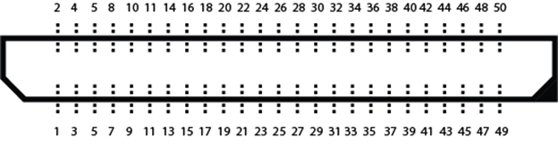
The GPIO port is a 50-position female Samtec connector, ERF8 which mates with a 50-position male Samtec connector ERM8. Figure 1 is a pin-out diagram of the female connector that terminates the BRCK GPIO Expansion.
Figure 1: GPIO pinout diagram

Table 1: GPIO-ATmega32U4 pin mapping
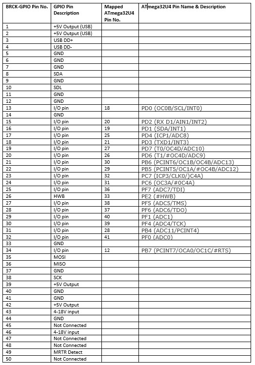
Figure 2: ATmega32U4 Microcontroller pinout diagram
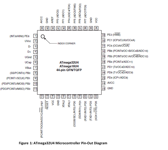
For detailed information about the microprocessor, see the ATmega32U4 Datasheet
We also make BRCK GPIO Expansion Boards which are compatible with Arduino Shields. The boards have header pin and screw terminal connectors for all the I/O and power input/output pins in addition to a USB (power and data) connector.
Table 2: GPIO Absolute Maximum Ratings
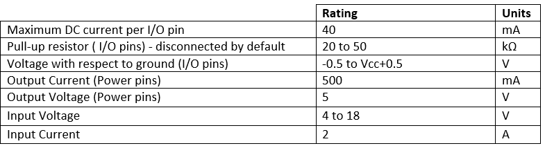
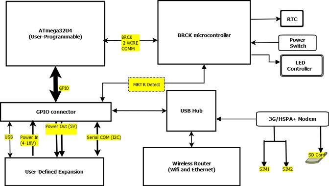
Figure 3: BRCK Block Diagram
We’ll have a more extensive datasheet available in the coming weeks, where we’ll also start testing out some different modifications to the BRCK using our own GPIO expansion board (more on that soon).
Yay, so great!
[…] RP-SMA) protégées par des sortes de capuchons en caoutchouc. Sous le BRCK, on trouve également un port GPIO qui permet, par exemple, de connecter des extensions à base […]